This is stage 4 of the Quick Start example for Machine Control Studio.
In this stage the example program is built into a user image, Machine Control Studio is taken online and the user image is downloaded to the target.
To begin this stage, the example project created in stages 2 and 3 should be open in the application editor. If the example project has been closed, reopen the example project. If you have followed the steps exactly, the project should be named “GettingStartedExample”.
To build the project, perform the following steps:
With the project open in the editor, select Build > Build from the Menu Bar, or press the F11 key on the keyboard. Machine Control Studio will proceed to build (or compile) the user project to verify syntax and configuration.
Step 2 – Check the results of the Build
The build should take only a few seconds to complete, maybe longer for larger projects, and the results of the build will be displayed in the Messages window. To view the Messages window (if not already visible), select View > Messages from the Menu Bar as seen in Figure 30 below.
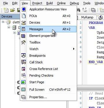
Figure 30 – Select View > Messages to check the results of the Build
Within the Messages window should be the results from the Build action. If all steps of this Getting Started Guide were followed properly, then you should not have any build errors. The window should show “Compile complete – 0 errors, 0 warnings” as seen in Figure 31 below.
If you do encounter build errors, they will be listed in this window with each error listed individually as a single line item. You can double-click on a given error and the editor will bring you to the line of code in the Program or Function Block that contains the error. Note that sometimes a single syntax mistake can cause multiple build errors. Simply work your way down the list of errors one by one. After each error is fixed, rebuild the project using the same steps as mentioned earlier. Continue this process until each error is removed from the Build Error list and the project compiles without any errors or warnings.

Figure 31 – The Messages View
Note that the Message Window can be undocked from its current location and moved to a new location as desired, or left positioned as default. Additionally, you can use the pin icon in the upper right-hand corner to make the window remain open all the time, or unpin it to allow it to hide automatically when not using it.
Also notice that the Messages window has a feature called “Precompile” in the bottom left-hand corner that basically shows the results of the real-time compiler that runs in the background. If you are editing your program or function block and type a syntax error, the Precompiler will notify you of the error before you do a full build action.
Step 3 – Check the Application Resources
Once the project has built without any errors or warnings, it is essentially ready to be downloaded to the Unidrive M Onboard target. One thing we need to verify before downloading is that the project image will fit within the available resources of the onboard target. To verify the image size, select View > Application Resources View from the menu bar. The Application Resources tab should appear, and you simply need to verify that the ROM Used and RAM Used meters are not beyond 100%. If you have followed each stage of the Getting Started Guide properly, the project should be well within the available resources as shown in Figure 32 below.
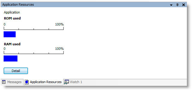
Figure 32 – The Application Resources View
If the ROM/RAM Used values do not exceed 100%, then the project is ready to be downloaded.
If the ROM/RAM Use values exceed 100%, then it is necessary to reduce the program size until it fits within the available resources. Alternatively, you could chose to switch to using a pluggable applications module as the target instead of the onboard target.
Connect the RS485 cable between a COM port (or USB Port) on the PC and the RJ45 on the front of the Unidrive M. Make a note of the PC COM port which the cable is connected to because you will need this information later. In the case of a USB comms cable, this may be a virtual COM port that you need to look up in the Device Manager tool in MS Windows.
Step 5 – Going Online (Logging In to the Target)
The process of downloading the project to the target begins by logging in to the target device. This is done by selecting Online > Login from the Menu Bar as seen in Figure 33 below.
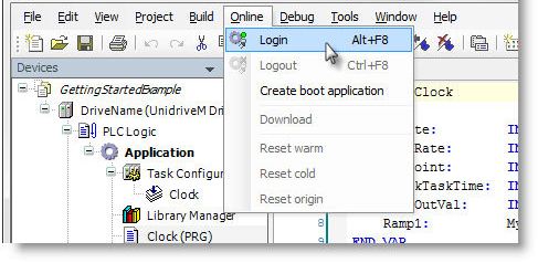
Figure 33 – Logging In to the Controller
This will cause Machine Control Studio to make a connection between the PC and the hardware target. If the active project has not established communications before, a dialog will appear notifying the user that there is no active communications path defined, and asking if you wish to set a path. Click Yes to define the comms path. After clicking Yes, the Drive Tab and Communications Settings subtab will open up as seen in Figure 34 below.
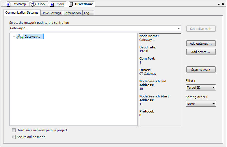
Figure 34 – Communications Setting View
The communications path to the device is referred to as a Gateway. The Gateway must be configured with the proper settings to match the controller so that communications may be established. The controller (or drive) settings can be found on the Unidrive M using the drive keypad by checking the following parameters.
| • | M00.P036 has the Baud Rate setting (19200 by default) |
| • | M00.P037 has the Node Address setting (1 by default) |
Higher baud rates will work should you chose to modify the default comms settings. It is important that both the drive and the Machine Control Studio software settings match in order to establish communications. Note that baud rates up to 115.2kbaud can only be achieved using the USB CT485 lead.
The right side of the window in Figure 34 above shows the current Gateway settings. To modify the settings, right-click on the Gateway and select “Edit Gateway…” to bring up the Gateway setup dialog as found in Figure 35 below.
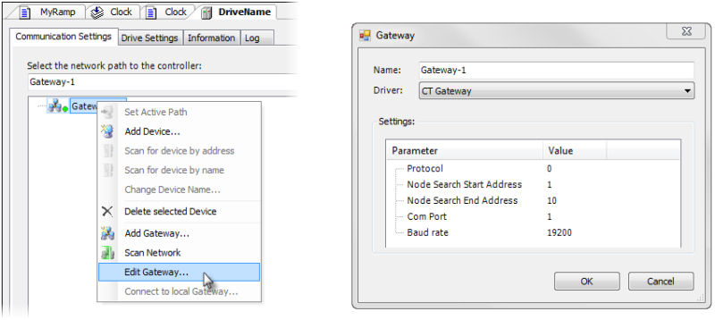
Figure 35 – Editing the Gateway Settings
Adjust the settings as necessary to match the drive and select OK to apply those settings. Once applied, click the “Scan Network” button on the right side of the Communications Settings view. Doing so will cause Machine Control Studio
to interrogate the network for devices between the Node Search Start Address and End Address defined on the Gateway settings dialog. Once a device(s) is found, it will appear as a branch under the Gateway as seen in Figure 36 below.
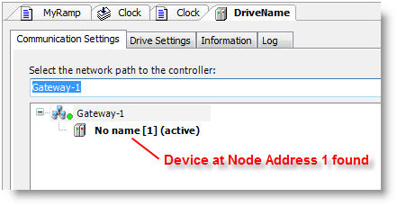
Figure 36 – Device Detected on Gateway
Step 6 – Download the Project to the Target Device
Once the Gateway has been configured properly, and the device has been detected, select the Online > Login from the menu bar again, or click on the Login icon as identified in Figure 37 below.
![]()
Figure 37 – Login Icon on Toolbar
If the Gateway is configured properly, the Login should succeed and a dialog will appear notifying the user that the target device (Unidrive M) contains a different version of an Application, and asks if you wish to perform a download to load the new Project onto the controller. Answer Yes to download the project. Doing so will cause Machine Control Studio to rebuild the application (in case any changes were made since the last Build), and also generate the image that runs onboard the target. The image should then download to the target and Machine Control Studio will remain online with the device.
At this point, you should be online and the project should be downloaded to the device.
This is the end of stage 4 of the Quick Start example.
The next Quick Start stage is:
The previous Quick Start stage was: