This is stage 3 of the Quick Start example for Machine Control Studio with the Unidrive M Onboard target.
In this stage, we will investigate how to modify the user program to perform the desired operation. At the end of the stage, the program will be ready for building and downloading to the target device.
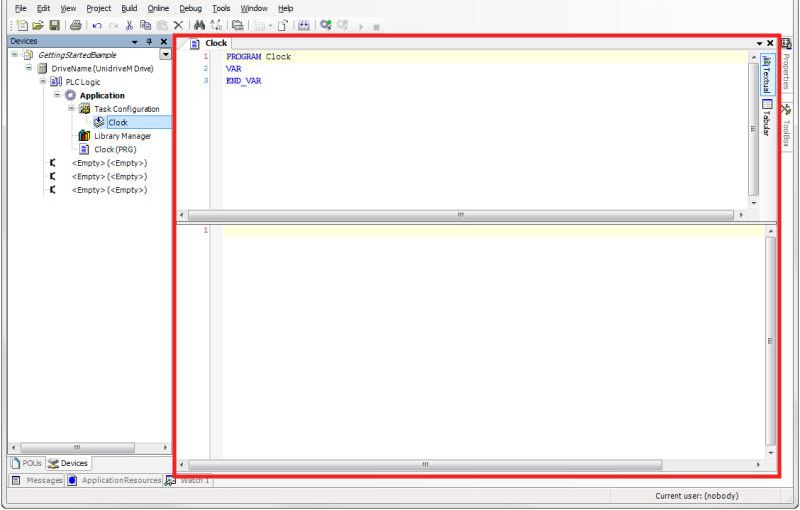
Figure 8 – Program Editor View
The program editing view is broken into two sections. The top section is the Variable Declaration section and is used to declare program variables used within this program. The bottom section is the Coding section and this is where the actual program code will be created.
Step 2 – Declare Program Variables
To use a variable within a user program, that variable must first be defined in the Variable Declaration section of the program view. To declare a program variable, simply insert a new line between the labels “VAR” and “END_VAR”. Then insert the desired variable name and the data type in the following format:
VariableName: DataType;
Figure 9 below is an example which declares a user program variable named “TestVar” with a Data Type of Integer.
VAR
TestVar: INT; // An example of declaring a variable
END_VAR
Figure 9 – Example of Declaring a Variable
Note that by default, Machine Control Studio will automatically indent your variable and bold and color the data type identifier keyword. The separation between the colon and the data type can be one or more spaces as desired. To create a comment for a variable, the syntax is two forward slashes “//” followed by your desired comment. The two forward slashes indicate a single line comment. If the comment runs over multiple lines, you will either need to put “//” at the beginning of each line, or use the multi-line comment syntax of “(*” and “*)” or “{“ and “}”. Anything between those character combinations is interpreted to be a comment.
Commenting Declared Variables
As in any coding language, comments are a vital part of creating a quality Machine Control Studio program. Comments allow your code to be easily read by other users, allow you to remember sections of code that you haven’t touched for long periods of time, help to make code more portable or re-usable, as well as aid in writing and debugging your program. Because Machine Control Studio uses IntelliSense tools to help you create programs, it is important that comments are properly placed in the variable declaration section, otherwise the Intellisense tool will not interpret the comment correctly. If a comment is not placed in the proper location, it can look fine visually when reading it, but IntelliSense may associate the comment with the incorrect variable. Valid comments must appear above or on the same line as the declared variable. Figures 10 and 11 below are examples which show how to correctly and incorrectly comment your declared variables.
CORRECT
VAR
TestVar1: INT; // Valid comment location for TestVar1
// Valid comment location for TestVar2
TestVar2: INT;
END_VAR
Figure 10 – Correct method of commenting Declared Variables
INCORRECT
VAR
TestVar: INT;
// Not a valid comment location for TestVar1
END_VAR
Figure 11 – Incorrect method of commenting Declared Variables
As many variables as desired may be created within the Declaration section. The only key to this is that all variables must be between the VAR and END_VAR labels, and each one must be given a proper Data Type.
Initial Values for Declared Variables
Variables may be initialized with a non-zero value if desired. Figure 12 below shows how to properly give a declared variable an initial value.
VAR
// Gives TestVar1 an initial value of 5
TestVar: INT :=5;
END_VAR
Figure 12 – Declaring an Initial Value for a Variable
Note that one or more spaces are allowed between the Data Type and the operator and the value.
All variables not explicitly given an initial value will be initialized with a value of zero; however, it is good programming practice to always define an initial value, even if that value is zero.
Auto-Declaration of Variables
A variable can be declared automatically by just using the desired variable name within the program coding section. When the user enters a carriage return, then the Auto Declare dialog will pop up requesting the user to enter the declaration data for the new variable. Figure 13 below shows an example of the Auto Declare dialog.
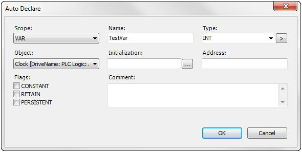
Figure 13 – Auto Declare Dialog Box
The Name field of the Auto Declare dialog will automatically be populated with the new variable name that was typed into the program. The Type field will default to the INT data type, unless the system can determine what type of variable you want to create based on the context of the line of code. For example, if you are creating a new variable to be used as the input or output of a function block, the system already knows what data type the function block is expecting, and populates the Type field accordingly. Initial Values and Comments can also be added using this dialog as desired.
Click OK to accept the changes when the declaration properties have been filled in. Machine Control Studio will then automatically add the declaration information into the Variable Declaration section of the program view.
Note that any variables declared within this program declaration section are local only to this program. In other words, other programs or function blocks do not have access to these variables. If it is required to have access to a variable outside of a given program or function block, the variable must be declared in a Global Variable List. Global Variable Lists are not covered in this Quick Start guide. Refer to the Machine Control Studio help system for help on Global Variable Lists.
A little more about variables:
| • | Variable names cannot begin with a numeric character. |
| • | Variable names cannot contain spaces or other special characters (i.e. @, #, $, etc.); However, underscores characters are allowed but there may not be more than one in a row. |
| • | Variables are NOT case sensitive (example: TESTVAR, TestVar, and testvar are all the same variable). |
| • | The length of variable names is not limited. |
| • | Some words are reserved and cannot be used for variable names. For a list of reserved words, right-click in the program code section and select Input Assistant > Keywords. |
For this example program, declare the following variables and give them the initial values as defined below. Give each variable a basic comment as desired. When complete, your Variable Declaration section should look similar to the code found in Figure 14 below.
PROGRAM Clock
VAR
UpRate: INT := 500; // Defines the count up rate of the ramp
DownRate: INT := 500; // Defines the count down rate of the ramp
Setpoint: INT := 5000; // Defines the target of the ramp
ClockTaskTime: INT := 0; // Update rate of the Clock task
RampOutVal: INT := 0; // Output value from the ramp block
END_VAR
Figure 14 – Example Program Variable Declaration
These variables will be used to populate the inputs/outputs of a Ramp function block created in the next step.
For a list of all supported data types in Machine Control Studio refer to the help file section Programming References > Data Types > Standard Data Types. Note that for the Unidrive M Onboard target, the 32-bit real (REAL), 64-bit integer (LINT and ULINT), and WSTRING data types are not supported.
In this step, we will add our first Function Block to the user program.
This is a good opportunity to introduce the POU, or Program Organization Unit. Don’t be confused by this name “POU”. It is simply a generic term used in the software to describe any component within the programming environment. Individual POUs are combined together to create the overall application program. POUs come in the following three types:
Program – A Program POU is a high-level object that runs on a specified task. A Program POU can have its own code to perform a task, but may also call other low-level POU’s (i.e. functions or function blocks) to perform more specific tasks.
Function Block – A Function Block POU is a lower-level object containing some program functionality, and is used within a Program POU. Imagine a Function Block as a sort of subroutine that is called by a program. Function Block POU’s can have one or more Input Variables and one or more Output variables. Once a Function Block POU is created, it can then be used within a Program POU or another Function Block POU. When a Function Block is declared, it allocates memory to hold the instance data, therefore allowing a Function Block to be used multiple times in a program.
Function – A Function POU, much like a Function Block POU, is a lower-level object that performs some specific operation within a Program POU. A Function also acts like a subroutine that is called by a program. The difference between a Function and a Function Block is that a Function only has a single return variable/type. The single return functionality allows the function to be called as an operation in the Structured Text language (i.e. ResultVar := Function(Input1, Input2, Input3)). The output of the function will be assigned to the variable named ResultVar in the previous example. Another difference between a Function and a Function Block is that a Function does not retain data whereas a Function Block does. A typical example of a Function POU is a math operation that is passed one or more input values, and only returns a single result value.
For best practice, when creating Function Block or Function POUs, try not to read or write drive parameters inside the function. Rather, if a drive value is needed for the function, pass the drive value in or out as an input or output argument.
Now that we have defined the POU, we will add a Function Block POU to our Clock program. To do this, right-click on the Application item in the Devices Tree on the left side of the application.
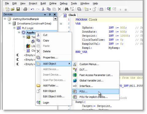
Figure 15 – Right-click on Application to Add a POU
When the context menu appears, select Add Object > POU…. This will cause the Add POU dialog to appear as seen in Figure 16 below.

Figure 16 – The "Add POU" Dialog Box
In the Add POU dialog, give the function block a name in the Name field. Use a name of “MyRamp” or any other name of your choosing. Note that POU names follow the same basic rules of variable names as described in Step 2 above. Select the Function Block type radio button. Finally choose Structured Text for the Implementation Language of the Function Block. Click Open to create the Function Block. When complete, the application should open the Function Block Editor for the newly created function block as seen in Figure 17 below. Note that the Function Block Editor looks almost identical to the Program Editor. This makes some sense because, remember that Programs and Function Blocks are simply two slightly different types of POUs.
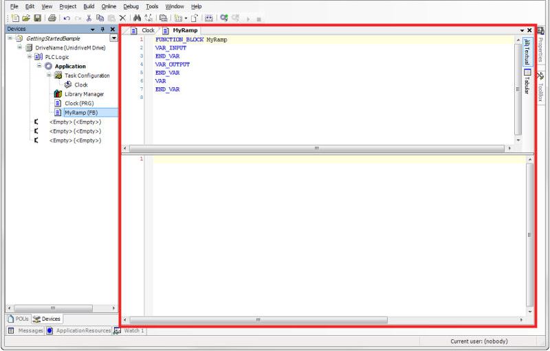
Figure 17 – Function Block Editor
Upon closer inspection you will find that the Variable Declaration section looks a bit different than it did for a normal program. The difference is that there are several types of variables to be declared rather than just basic variables. Because this is a Function Block, you must define Input and Output variables in addition to the standard variables used within the Function Block. The Input Variables are the values passed into the block, and Output Variables are the values (or results) passed out of the block. The Variables Declaration section allows you to declare variables of all three types. See Figure 18 below for details.
Function Block Variable Declaration
FUNCTION_BLOCK MyRamp
VAR_INPUT
// Input variables are declared here
END_VAR
VAR_OUTPUT
// Output variables are declared here
END_VAR
VAR
// Standard variables used within the FB are declared here
END_VAR
Figure 18 – Function Block Variable Declaration
For this example, declare the variables defined in Table 1 below. Be sure to declare the variables in the right location based on the type of variable (i.e. Input, Output, or Variable). Modify the comments as desired.
Var Type |
Name |
Data Type |
Comment |
Input Variable |
Target |
INT |
Target value for ramp |
Input Variable |
CountUp |
INT |
Rate for ramping up (units/sec) |
Input Variable |
CountDown |
INT |
Rate for ramping down (units/sec) |
Input Variable |
TaskTime_msec |
INT |
Update rate of task FB is used in |
Output Variable |
Out |
INT |
Output ramp value of function block |
Variable |
OutTemp |
INT |
Temporary output ramp value |
Table 1 – Function Block Variables
Once the above variables have been declared, the program code can be added in the Coding Section of the editor. Copy the code below and paste it into the Coding Section of the Function Block.
IF Target > Out THEN // Ramp output up (accelerate) to Input Target value
// Add one update increment to ramp output
OutTemp := OutTemp + (CountUp * TaskTime_msec / 1000);
// Clamp the output
IF OutTemp > Target THEN
OutTemp := Target;
END_IF;
ELSIF Target < Out THEN // Ramp output down (decelerate) to Input Target value
// Subtract one update increment from ramp output
OutTemp := OutTemp - (CountDown * TaskTime_msec / 1000);
// Clamp the output
IF OutTemp < Target THEN
OutTemp := Target;
END_IF;
END_IF;
Out := OutTemp; // Set Output
Without going into great detail, the ramp code above will increment or decrement the ramp output value a certain amount based on the specified ramp input values and the task update time. Understanding the exact operation of the program is not what is important, so don’t feel like you need to understand the functionality in detail. The goal of this Getting Started Guide is simply to familiarize the user with the programming interface and all of its components.
The MyRamp Function Block is now complete. If we were to look at MyRamp as a block diagram, it would appear as seen in Figure 19 below.
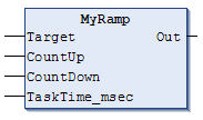
Figure 19 – MyRamp Function Block as Block Diagram
Note that even though the MyRamp function block was created using the Structured Text language, MyRamp can be used within programs created in any of the IEC-61131 languages. It will automatically appear in the proper format.
You should now see the MyRamp function block appear in the Devices tree view on the left side of the user interface as seen in Figure 20 below.
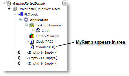
Figure 20 – MyRamp Function Block appears in Devices tree
Once the MyRamp Function Block is created, it doesn’t do anything by itself. It must be used or called from a within a Program POU to be executed. Let’s go back to our Clock program and use our new MyRamp Function Block.
In this step, we will use the new MyRamp Function Block that was created in the previous step.
When using an existing Function Block within the program, we can use the Input Assistant functionality of Machine Control Studio to create an instance of the block. You may be asking yourself, “Why do we create an instance of a function block?” The answer to this is because a function block itself is simply a template which can be reused as many times as desired throughout your program(s). When calling a function block in a program, you are actually calling an instance of the function block template. If a function block is used multiple times in a program, it will likely be passed different input data each time, and therefore you need multiple instances of the block to keep track of the various input and output data variable values.
To use the Input Assistant, right-click on the line of the Coding Section of the program in which you wish to call your function block as seen in Figure 21 below.
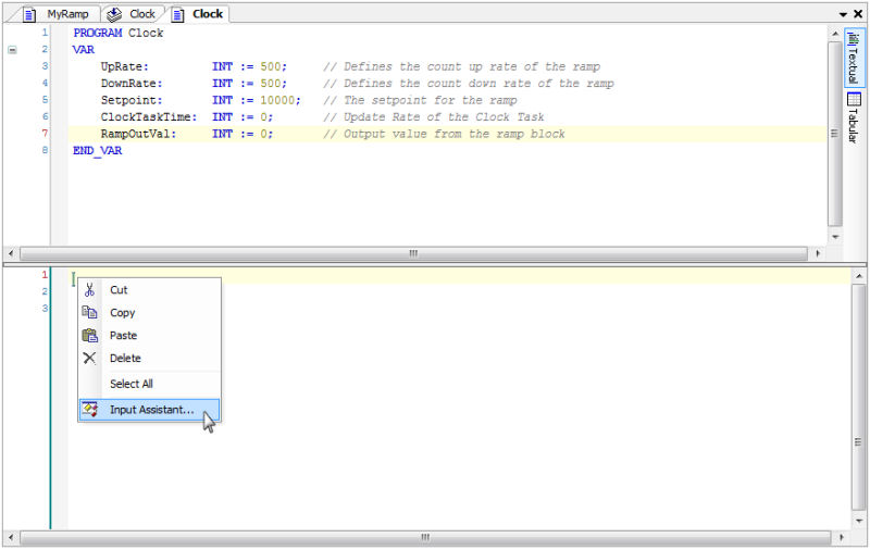
Figure 21 – Right-click to select Input Assistant
Doing so will bring up the Input Assistant dialog which allows the user to select an existing variable, module, function block, etc. to insert into the program. Figure 22 below shows an example of the Input Assistant dialog box.
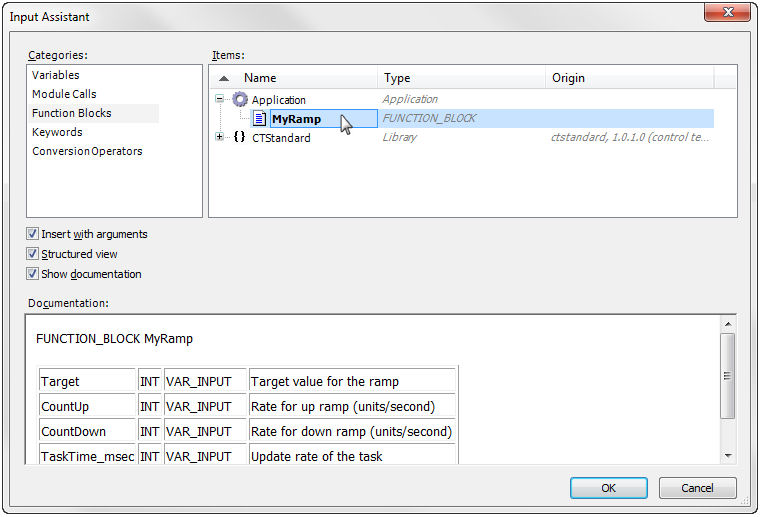
Figure 22 – Input Assistant Dialog Box
To insert our function block created in the previous step, first select “Function Blocks” from the Categories field. Then expand the “Application” branch in the Items field. We are looking in the Application branch, because we created this function block within our application. If it was a function block from one of the standard libraries, or a third party library, we would choose the appropriate library branch containing the desired function block in the Items field instead. Locate and click on the MyRamp function block. Notice how the Documentation section at the bottom of the dialog shows the input and output variables for the function block. Note how it has picked up the comments for each input and output variable that we entered when declaring the variables within the function block editor! Finally, click OK to insert the function block into the clock program.
Once you click OK to insert the function block, the Auto Declare dialog should appear to help you declare a new instance of the MyRamp function block, as seen in Figure 23 below. Set the Name field to “Ramp1” and click OK.
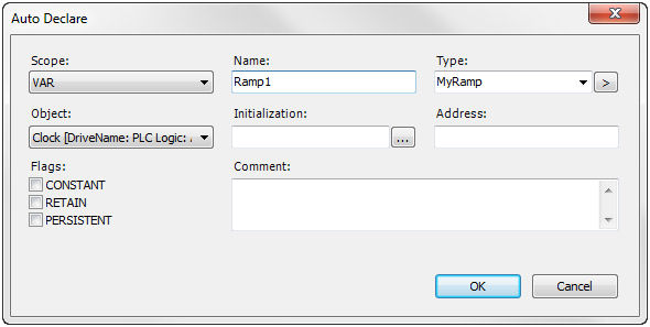
Figure 23 – Declare an instance of MyRamp
When complete, the function block call will be added to the Coding Section, and a declaration of a variable called Ramp1 of data type MyRamp will be created in the Variable Declaration section. Your screen should now appear as seen in Figure 24 below.
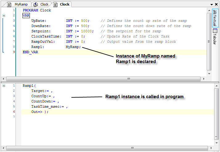
Figure 24 – Screen after Input Assistant adds Function Block
When the Input Assistant inserts the call to Ramp1 in the program, it breaks each of the Input and Output Variables onto separate lines for clarity. The following line of code has all the arguments on a single line and would work just the same as Figure 24 above.
// This is the same as breaking into multiple lines as in Figure 24
Ramp1(Target:= ,CountUp:= ,CountDown:= ,TaskTime_msec:= ,Out=> );
Note how the Input Variables have the “:=” operator next to them so that we can assign a value or variable to them, and the Output Variable(s) have “=>” next to them which means a value will be assigned to whatever variable is specified. Let’s use the variables created several steps ago to pass data values into the function block. Enter the variables into the function block call as seen in Figure 25 below.
Ramp1(
Target:= Setpoint,
CountUp:= UpRate,
CountDown:= DownRate,
TaskTime_msec:= ClockTaskTime,
Out=> RampOutVal);
Figure 25 – Adding Variables to the Function Block call
This means that we will pass the values of the declared variables into the Ramp1 function block. Once you have completed assigning variables to the function block parameters, we will add some additional code to the Clock Program.
When ready, copy and paste the necessary code so that your Clock program looks as shown in Figure 26 below.
// Read the Clock task time from the drive
IF ClockTaskTime = 0 THEN
ClockTaskTime := DINT_TO_INT(M11.P055);
END_IF
// Call the ramp function block
Ramp1(
Target:= Setpoint,
CountUp:= UpRate,
CountDown:= DownRate,
TaskTime_msec:= ClockTaskTime,
Out=> RampOutVal);
// If we have reached the setpoint ramp, in the other direction
IF RampOutVal = Setpoint THEN
Setpoint := -Setpoint;
END_IF
Figure 26 – Complete Clock Program Code
The program is now complete. Save the program by choosing File > Save Project from the menu bar.
Calling Function Blocks
When calling a function block within a program, it is not mandatory to pass values to all input parameters or read all output parameters. For example, if we wished to call the Ramp1 function block, but did not want to write to the CountUp or CountDown arguments, we could simply eliminate them from the call instruction as seen in Figure 27 below.
// Call Ramp1, but do not send data to CountUp or CountDown params
Ramp1(
Target:= Setpoint,
TaskTime_msec:= ClockTaskTime,
Out=> RampOutVal);
Figure 27 – Calling Function Block without all I/O data
If this method of selected data is used, then the function block will use the last value of the variable for processing the block. If no value has ever been written to a function block variable, then it will use the value defined in the variable declaration section of the function block.
Alternate Method to Access Function Block Data
The way that we have used variables to pass data into the Function Block thus far is referred to as indirect access to the Function Block. We could use another method to pass data into our get data out of the function block by using what is called a direct access method. The example below shows the difference between the indirect and direct access methods of passing a value of 1000 into the CountUp input parameter on the Ramp1 block.
Indirect Access of Function Block Data
UpRate := 1000; // Set UpRate to 1000
// Value of 1000 gets indirectly passed to Ramp1 – CountUp parameter
// through the UpRate variable
Ramp1(
Target:= Setpoint,
CountUp:= UpRate,
CountDown:= DownRate,
TaskTime_msec:= ClockTaskTime,
Out=> RampOutVal);
Figure 28 – Indirect Access of Function Block Data
Direct Access of Function Block Data
// Value of 1000 gets directly passed to Ramp1 – CountUp parameter
Ramp1.CountUp := 1000;
Figure 29 – Direct Access of Function Block Data
This direct method can be much more efficient since it does not require the allocation of a variable just to hold the data to be passed into the function block. Note that simply writing directly to the input parameter of a function block as seen above does not initiate the function block as shown in the Indirect method.
This is the end of stage 3 of the Quick Start example.
The next Quick Start stage is:
The previous Quick Start stage was: